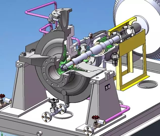
API 610 standard (i.e. API pump) always puts safety and reliability in the first place, even at the cost of sacrificing part of the pump efficiency, such as using rigid shaft design, in order to ensure that the dynamic / static parts are not easy to bite under any working conditions, increase the gap between the mouth ring and so on. There are many clauses concerning safety and reliability, which are excerpted as follows.
2.1 clause 6.1.11 [2] for all application conditions, it is better for the pump to have a stable flow head curve (i.e. the head curve rises continuously until the shut-off point). If the parallel operation is specified by the buyer, it must have such a stable flow head curve. If parallel operation is specified, the head rise on the curve shall be at least 10% of the head at the rated flow point.
[interpretation] if the head curve has humps, there will be two different flow points corresponding to the same head, which is easy to cause misoperation (or false alarm). If the head rise is too small, that is, the change of pump outlet pressure is too small, it will not be convenient for users to adjust and monitor on site. However, the head rise should not be too large (especially for multi-stage pump), otherwise the design pressure level of downstream pipeline will be affected and the investment cost will be increased. In engineering practice, the head rise to the critical point is usually 10-20%, but for high-pressure multi-stage pump, the head rise is usually relaxed to 10-25%.
2.2 clause 6.1.12 shall give the pump a preferred working area, which is located in the range of 70-120% of the flow rate at the best efficiency point of the impeller provided. The rated flow point should be located in the range of 80-110% of the flow rate at the best efficiency point of the impeller provided.
[interpretation] the optimal choice is that the rated flow point of the pump is on the right side of the optimal efficiency point, while the normal operation point is on the left side of the optimal efficiency point. However, it is difficult to make such a satisfactory choice in practical application. However, as a guiding principle, the operating condition of the pump should be in or close to the above range.
2.3 article 6.1.15 for pumps with single-stage head exceeding 200m and single-stage power exceeding 225Kw, special measures are required to reduce the frequency vibration of impeller blade and low-frequency vibration at small flow rate. For these pumps, the radial clearance between the guide vane and the outer circumference of the impeller blade is at least 3% of the maximum impeller tip radius (for guide vane pumps) and 6% of the maximum impeller tip radius (for Volute Pumps).